
.jpg)
Parallel Resistance Recap
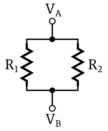
When two resistors are connected between the same two nodes, they are in parallel. Resistors connected in parallel have the same voltage drop, but the currents flowing through these resistors are not necessarily the same.
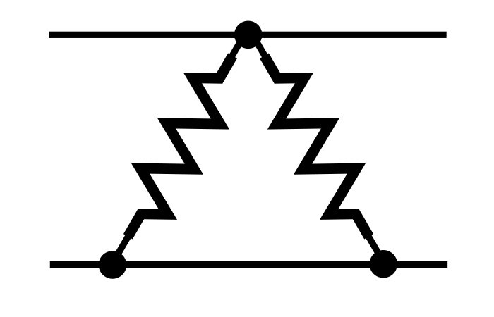
Electrically parallel resistors don’t always look like two parallel lines. The following diagrams are examples of parallel resistive networks.
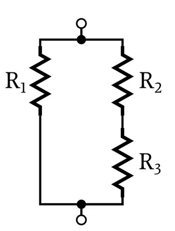
Individual resistors can be in parallel, but in a more general sense, one source of resistance can be in parallel with another source of resistance. In the following diagram, one resistor is in parallel with resistance consisting of two resistors.
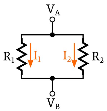
Each current pathway leading from one node to another is called a branch. In the following diagram, I1 and I2 are branch currents.
For more information on parallel resistance, please read the first article in this series.
Calculating Branch Currents
The current flowing through parallel resistors is governed by Ohm’s law, which states that voltage (V) is equal to current (I) multiplied by resistance (R).
If we rearrange this equation so that it solves for current, we have
Thus, once we know the voltage across a parallel network, we can calculate the current flowing in each branch by dividing the voltage by the branch resistance.
Let’s look at an example:
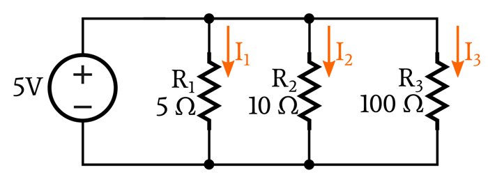
Because this circuit does not contain any components that separate the parallel network from the voltage source, we know that the voltage across the network is 5 V. Thus, we can calculate the three branch currents by inserting the resistance value for each branch.
Equivalent Resistance for Parallel Networks
Next, let’s calculate branch currents for the following circuit.
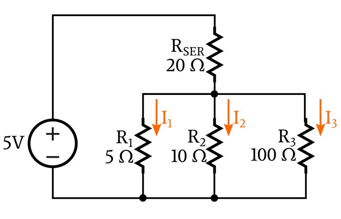
We see right away that this configuration is more difficult to analyze. In order to calculate the branch currents, we need to know the voltage across the parallel network (VPAR). In the previous circuit, VPAR was equal to the supply voltage, but in this circuit, we can’t immediately establish the value of VPAR because part of the supply voltage is dropped across RSER, which is in series with the parallel network. If we knew VRSER, we could find VPAR:
But in order to calculate the voltage across RSER, we need to know how much current is flowing through RSER, and we can’t calculate RSER’s current because we don’t know the values of I1, I2, and I3. How do we proceed?
This leads us to a very important concept, namely, equivalent resistance. If we are interested in knowing how the parallel network behaves when treated as a unified electrical system, we can replace the parallel resistors with one resistor. We can then analyze the circuit using this equivalent resistance (REQ), and the current flowing through REQ will be equal to the current flowing through the entire network:
Calculating Equivalent Resistance
The equivalent resistance for any parallel network can be calculated as follows:
When you have only two resistors in parallel, you can also use the following formula:
This equivalent resistance value is not identical to the parallel network; you can’t replace two (or three, or ten) resistors with one resistor and say that the circuit is exactly the same.
However, the equivalent resistance does accurately duplicate the overall electrical properties of the network. This means that you can use REQ to determine the total current flowing through the branches, and this total current can help you to determine the voltage across the parallel network.
Circuit Analysis with Equivalent Resistance
Let’s apply our knowledge of equivalent resistance to the four-resistor circuit shown above. First, let’s find REQ.
Now, if we replace the parallel network with a single equivalent resistor, the circuit looks like this:
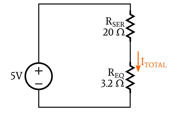
We can use Ohm’s law to calculate ITOTAL:
Again applying Ohm’s law, we can calculate the voltage across the network as follows:
Now we can calculate the branch currents as we did in the first example.
The Effect of Adding Parallel Resistance
If you examine the formula that we use to calculate the equivalent resistance of a parallel network, you will find that adding any amount of parallel resistance will always result in a lower equivalent resistance. Even adding a very large parallel resistance will cause the resistance of the entire network to decrease. It follows that the equivalent resistance of a parallel network will always be smaller than the smallest individual resistance in the network.
This may seem counterintuitive at first, but it makes sense if you think about it this way: Any quantity of resistance that you connect between two nodes will allow at least a little bit of current to flow through this new branch. By “adding” resistance, you are actually creating a new pathway for current, and an increase in overall current corresponds to a decrease in overall resistance.
Conclusion
We can use Ohm’s law to calculate branch currents in a network of parallel resistors. However, this requires us to know the voltage across the network, and we can’t always determine this voltage simply by looking at the circuit.
An important circuit-analysis technique involves replacing resistors connected in parallel with one resistor whose value is equal to the equivalent resistance. If your calculations produce an equivalent resistance that is larger than (or equal to) any resistor in the network, something went wrong, because even the smallest resistor in a parallel network is larger than the equivalent resistance.